
EverLights Self-Installation
An overview of how to install your EverLights.
Want to shop our DIY solutions? Click here.
An overview of how to install your EverLights.
Want to shop our DIY solutions? Click here.
Never cut any wires with the lights powered. The lights are powered anytime they are plugged into a power source, whether the lights are on or not. Always install with the lights unplugged from all power sources.
Connect like to like wires. The wire labeled “EverLights” only connects to other wires labeled “EverLights”. Same deal for the other three wires.
Keep the direction of the lights constant. Every light has an input and output. They must always connect in to out. There is an arrow on the back of every light and on the front of every data buffer. Ensure all arrows are pointing in the same direction.
When it comes to simple Christmas light installation, homeowners turn to EverLights. Our patented design means EverLights are the easiest permanent holiday lights to install. Whether you’re an experienced tradesman or a weekend warrior, we’ll walk you through the system and installation procedure with the following guide.

EverLights Bridge Setup Video
With the Bridge connected, you now need to pair any wireless receivers you have. Make sure to follow this step in close proximity to the Bridge to ensure a simple connection. Do not install the wireless receiver outside before pairing with the Bridge. To put the bridge in pairing mode, press the black button on the back of the bridge. This will put the bridge in pairing mode for two minutes.
To put the wireless receiver in pairing mode, use the included wire-nuts to attach a power supply and plug the wireless receiver into an outlet. Like pressing the pairing button on the Bridge, plugging the wireless receiver into power will put it into pairing mode for two minutes. It does not matter what order you do this in, it only matters that both units are in pairing mode at the same time. Now go into the EverLights app and navigate to Menu/Settings/Zones and click the plus icon in the bottom left corner. Follow the instructions on the screen to pair your zones.
The Wireless Receiver connects directly to the lights and tells them what to do by receiving a low frequency radio signal from the bridge at distances up to half a mile. It is always best to install the wireless receiver on one end of the house or another. If you install the wireless receiver with lights on both sides of it, any patterns and animations will not look their best as they will converge or diverge from that point.
In the ideal situation, an eave outlet or other power source will be available on one end of the house. If no power is readily available, the garage is typically the best location for the wireless receiver. Wherever you are able to install the wireless receiver, make sure it is connected directly to the power supply with two of the included pink butt splice connectors.
If power is not where you want the receiver to be, do not insert additional wire between the power supply and wireless receiver, otherwise it will run the risk of not working properly. Instead, connect the wireless receiver directly next to the power supply, attach a data buffer to the output wires of the wireless receiver, and run unlit wire to where your lights start.
A data buffer is important to send a strong data signal and will be discussed in depth below. If the length of wire between the wireless receiver and first light is less than five feet, there is no need for a data buffer. Make sure the wireless receiver is installed in a dry location as it is splash resistant but not waterproof. Also ensure the wire connecting the lights to the wireless receiver has a drip loop to prevent water from running down the line and directly into the wireless receiver.
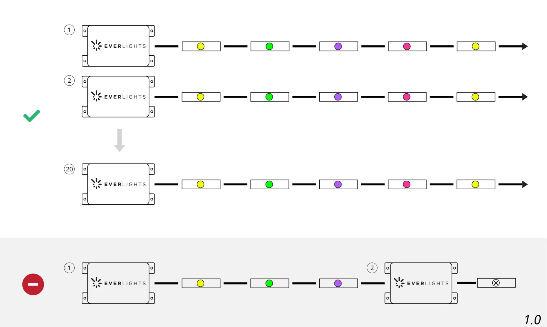
Up to 20 wireless receivers can be paired to a single EverLights Bridge, however they should never be wired into the same strand of lights.
EverLights Connection Video
Color Changing EverLights are directional and all arrows must be pointing in the same direction away from the wireless receiver. Each light has an arrow printed on the backside of the shell. Likewise, data buffers have an arrow label attached to the wiring.
EverLights utilize a 4-wire cable. Each wire is uniquely labeled to designate what it’s for:
EverLights = +5v positive wire
Solid White Line = Main data line
Solid Black Wire = Backup data line
GND = Ground wire
Wire designations can always be double checked with the labeling on the PCB. At connection points, always attach like to like wires.
Pro Tip: before crimping any wires together, always double check you are connecting the correct wires. Incorrect connections can be very frustrating to locate and fix later, it is much better to spend the extra time double checking wires before moving on than to come back later. For an extra layer of confidence, trace any cut wires back to the shell and verify the EverLights wire is connected to the +5v portion of the PCB.
EverLights can be cut and customized at any point, as long as the power is unplugged. Simply having the lights turned off in the app is not sufficient, they must be completely powered down. With power disconnected, cut and splice at any point to tailor the lights to your unique roofline.
Y-splits can be inserted at any point to carry the lights on in two directions. Any leg coming out of the Y-split with a section of unlit wire greater than 5 feet must have a data buffer inserted directly into the Y-split preceding the unlit wire to ensure a strong enough signal passes through.
EverLights Power Booster Installation
Color Changing EverLights are a 5 volt system. As lights draw on the initial power supply, the system needs to receive additional power to keep consistent color and brightness across the lights. There’s no perfect calculation as every roofline is different, but as a general rule of thumb a power booster is required every 75 feet. However, power is not directional so if you have a power supply at the beginning and end of 125 foot run, the load on each supply would be less than 75 feet and the lights would still have sufficient power.
Each Power Booster is only good for 75 total feet of lights though, so don’t expect to put a booster in the middle of a run of lights and get 75 feet in both directions. If a power source for a booster is not close to where the booster is tied in, you can extend the wire on the output end of the booster to get to the location power is needed. Avoid this strategy whenever possible as the unlit wire will provide resistance and result in a weaker boost where it ties in. For example, extending 50 feet of wire on the output end of the booster will effectively result in a negligible boost.